Publication Date: 16 February 1996
System Version: GCCS 2.1/Update 4
Web Page Created: 21 March 1996
Setup. To accomplish this lesson, you must have access to JOPES with the standard permissions associated with JD94TNG. The Person ID must have access to both hosts. In addition, you must have file space at both hosts and tape access at the primary host.
For you to provide service to your users, it is imperative that you first understand what the system is, how it works, and how to analyze the performance.
OBJECTIVE. From a list of capabilities, select those which are an accurate portrayal of the mainframe's operating characteristics.
File Management Supervisor. The FMS serves the user in a combination of ways to automatically sustain files in a readily usable, reliable condition, while providing the user with the degree of security for stored information. It provides file protection capabilities that maintain recovery details during system operation. It is an automatic system that controls where files are stored and protects them from being overwritten.
Security Control. Each user must have a valid PER, PJ, and PIC to log into the system. The system keeps a list that verifies the login attempts for security purposes. This verification compares the PER and the PIC to ensure it is valid. Once signed on, the system prevents you from accessing any program or file that you are not authorized to access. The system keeps track of your login security classification code (SCC) and prevents you from accessing files higher than your login SCC.
Job Flow. One of GCOS' functions is to ensure orderly and timely throughput of jobs. It manages this with Job Flow, which provides an orderly sequence of events. It uses priority codes to control when it executes, as well as controls the passing of information to the peripheral devices.
On-line System Development. The user is able to manipulate files, access other subsystems such as Convert, and run jobs using the Time Sharing System (TSS). TSS operates under the direction of GCOS and is a major dimension of an integrated, multidimensional information processing system. This means the system is capable of handling several users doing multiple jobs at the same time.
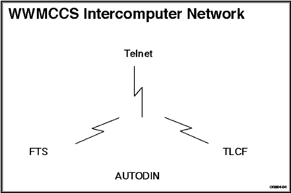
Networks. JOPES relies on WIN and Automatic Digital Network (AUTODIN) for data communications. A dedicated packet-switching data communications subnetwork interconnects WIN sites. It includes store-and-forward interface message processors (IMPS) and medium and wide-band communications circuits. The JDS Interface Processor (JDSIP) interacts with WIN to route and manage database updates between the primary and backup sites. Figure 10-1 depicts the network.

File Transfer Service (FTS). FTS allows the exchange of files containing all types of data between the host computers.
Teleconferencing (TLCF). TLCF allows planners to confer, exchange textual information, or assist in planning and decision making.
Mainframe Network Characteristics. The WWMCCS TS3 JOPES network currently consists of two Honeywell computers connected by the WIN Communications System. JOPES software provides real- time transaction processing, specifically the JDSIP and the JDS Update Processor (JDSUP) as shown in Figure 10-2.
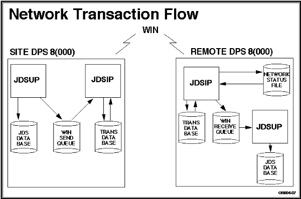
When a user sends an activity to the mainframe database, the JDSUP takes the transactions and updates the local files. It then places the transaction, with routing header information, on the WIN send queue. The JDSIP reads the transaction from the send queue, writes it to the transaction database (TDB) file, and gives it a number for tracking purposes.
The next transaction (as numbered) is selected from the TDB by the JDSIP and transmitted over the WIN. The remote JDSIP receives the transaction and places it on the WIN receive queue so the JDSUP can process it.
A network status file (NSF) update acknowledges the transaction transmission across the network to assist the TDBM in tracking transaction progress.
Note: If the site is out of the system, the TDB is held in storage until the site comes back up.
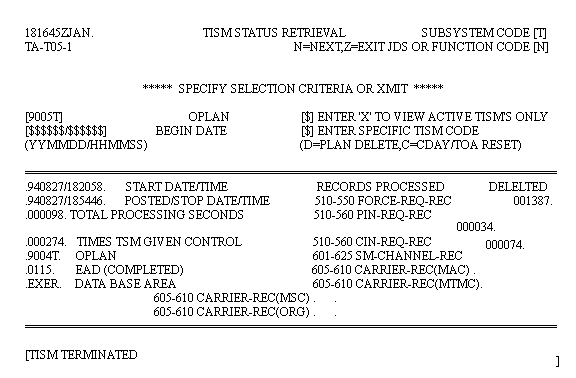
Transaction Independent Service Module (TISM). A TISM is also a transaction entered by a user that effects the database. It carries a lower priority for execution than a TSM and consequently takes longer to complete. TISMs start and stop as system resources allow. Because they take longer, there is a way to monitor a TISM's execution, the T5 Subsystem/Function.
| TISM STATUS RETRIEVAL | ||
|---|---|---|
| Step | Activity | Anticipated Result |
| 1 | At the JOPES Master Menu, type "t5" in SUBSYSTEM and FUNCTION CODE, and "e" in DATABASE. <RETURN>. | TA-T05, TISM STATUS RETRIEVAL (Fig. 10-3), screen displays. |
Note: Specific TISM code is used if you only want to check on a delete or C-Day reset. A C-Day transaction should not be in this system because execution will not happen in TS3. They are your only options for the specific choice.
 |
| TISM STATUS RETRIEVAL | ||
|---|---|---|
| 2 | Type "9005t" in OPLAN. <RETURN>. | TA-T05, TISM STATUS RETRIEVAL (Fig. 10-3), screen redisplays with TISM data, if any. |
| JDS UPDATE PROCESSOR ERROR MESSAGE DISPLAY (T8) | ||
|---|---|---|
| Step | Activity | Anticipated Result |
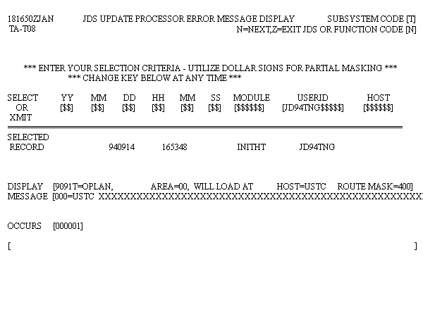
| 1 | Type "t8" in SUBSYSTEM and FUNCTION CODE, <RETURN>. | TA-T08, JDS UPDATE PROCESSOR ERROR MESSAGE DISPLAY (Fig. 10-4), screen displays. |
 |
| JDS UPDATE PROCESSOR ERROR MESSAGE DISPLAY (T8) | ||
|---|---|---|
| 2 | Type "jd94tng" in USERID. <RETURN>. | TA-T08, JDS UPDATE PROCESSOR ERROR MESSAGE DISPLAY (Fig. 10-4), screen redisplays. |
JOPES Database Characteristics. FMs should be familiar with the unique features of the JOPES database. The FM must understand the physical and practical system limitations and how the volume of information affects system performance. Prior to adding a TPFDD to the system, the FM should be familiar with the impact on system performance. The following are basic considerations:
Note: Database fill levels are not currently critical in the TS3 environment because there are presently so few OPLANs on the database. The information is presented to enhance your understanding of the system and not because it is critical to your duties.
JOPES Subfiles. These two databases are further subdivided into eight (8) subfiles. These divisions are similar to the cat/file string you use when saving data. It is simply a way of organizing information. They are a permanent part of the database and are accessed by S/F or JSIT commands instead of a string of commands. The subfiles are (record series shown in parenthesis):
Plan Information (200). This subfile is related directly to the A subsystem. The data entered through S/F A1 or A6 screens goes to this file.
Unit Information (400). This subfile is related to the C subsystem and is the file that holds unit (SORTS) information for sourced records in the plan.
Requirements (500). This subfile is directly related to the B subsystem. It holds the information as to what the requirement is, timing for movement, etc.
Scheduling and Movement (600). This subfile is directly related to the E subsystem and would contain all the carrier, schedule, and manifest information if the system were used for execution. It should be empty.
Nonstandard Cargo (700). This subfile is directly connected to the B subsystem, specifically the 7 and K functions. When you tailor cargo, it places that information in a separate location from the standard cargo.
Note: A standard UTC is often used many times within a plan. It only needs to write that information one time for all copies. If you write a nonstandard cargo detail, it is unique and needs a separate place for the information.
Force Module (900). This subfile is tied directly to the D subsystem. It is used to store force module information to include the chains that link individual requirements to the FMID.
Database Fill Levels. Figure 10-5 depicts the database fill levels.
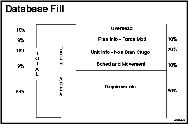
Management Considerations. The JOPES networked database is an Integrated Data System (IDS) structure. At 65 percent file saturation, the system response begins to slow down. At 80 percent, it degrades dramatically and a system crash becomes highly possible. At 90 percent, a crash is imminent. These critical levels apply to the individual subfiles, not total file space (does not share).
Note: Normally the DBSTAT Report is a TDBM function, however, we will briefly introduce it here. It can be run from the time sharing prompt by typing <FRN JDTDB/WIN/STATS/DBSTATS,Q,> and pressing <RETURN>. Then answer the dialogue screens that follow. Be advised that this program takes a long time to run. See Figure 10-6 for an example of the report.
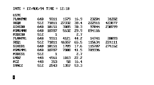 |
Note: 0 = Exercises, 1 = Real world in the first column of the DBSTAT file. As FMs, you are interested in only four of the listed subfiles, PLANFM, REQ, SCHED, and ASMUNM (nonstandard cargo and unit information). In the report, you are only interested in the fourth column. When the column reaches 65 percent, the FM should take action with the users to find data in that subfile that could be removed/eliminated.
OBJECTIVE. Given a WWMCCS environment, monitor the synchronization of an OPLAN on the JDS database and explain how to rectify an out-of-synchronization condition.
Methods of Synchronization. The method of synchronization used by the FM depends on the circumstances. On the mainframe, the SYNC subfile can be automatically or manually updated. We will cover the steps for both.
| SYNCHRONIZATION SUBFILE TRANSACTIONS | |
|---|---|
| Transaction Type | Description |
| INITHT | Initialize new plan number, reset plan type, and change OPLAN distribution. |
| PLNUAT | Change plan-status and non-trans-loaded. |
| RESTHT | Delete OPLAN (network or local) and reset C-day/TCCs (all or an individual TCC). |
| CDAYHT | Set C-day. |
| PFMUAT | Change plan-status. |
| STRYDT | Change plan-status. |
Note: Return to the Master Menu and ensure the PID is blanked out. The PID should be entered on the S/F HV screen because an OPLAN may be in delete status or hung somewhere, but deleted from your current site. Entering the PID at the Master Menu could result in an "OPLAN does not exist" message. Entering the PID at the HV level will show all sites the plan is deleted from, plus the action at the hung site.
| DISPLAY NETWORK SYNCHRONIZATION DATA AT TERMINAL | ||
|---|---|---|
| Step | Activity | Anticipated Result |
| 1 | Type "hv" in the SUBSYSTEM and FUNCTION CODE, "e" in DATABASE. <RETURN>. | IF-V01, OPLAN NETWORK STATUS (Fig. 10-7), screen displays. |
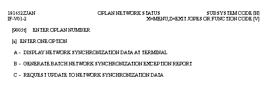 |
Note: There are three options available at Enter OPLAN Number: (1) an OPLAN, (2) All, or (3) Count. If a specific OPLAN is entered on the OPLAN Network Status screen (IF-V01), the user must be authorized access to the OPLAN. The All option can only be used by the Network FM. The Count option can only be used by the Network TDBM to review and reset S/F and User ID counts and other TDBM functions.
| DISPLAY NETWORK SYNCHRONIZATION DATA AT TERMINAL | ||
|---|---|---|
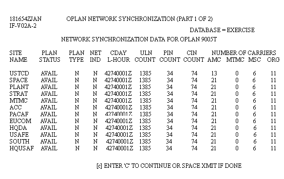
| 2 | Type "9005t" in ENTER OPLAN NUMBER, "a" in ENTER ONE OPTION. <RETURN>. | IF-V02A, OPLAN NETWORK SYNCHRONIZATION (PART 1 OF 2) (Fig. 10-8), screen displays. |
 |
| DISPLAY NETWORK SYNCHRONIZATION DATA AT TERMINAL | ||
|---|---|---|
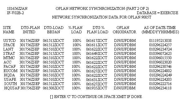
| 3 | Type "c" in ENTER 'C' TO CONTINUE OR SPACE XMIT IF DONE. <RETURN>. | IF-V02B, OPLAN NETWORK SYNCHRONIZATION (PART 2 OF 2) (Fig. 10-9), screen displays. |
 |
| DISPLAY NETWORK SYNCHRONIZATION DATA AT TERMINAL | ||
|---|---|---|
| 4 | Press <SPACE> <RETURN>. | IF-V01, OPLAN NETWORK STATUS (Fig. 10-7), screen redisplays. |
| GENERATE BATCH NETWORK SYNCHRONIZATION EXCEPTION REPORT | ||
|---|---|---|
| Step | Activity | Anticipated Results |
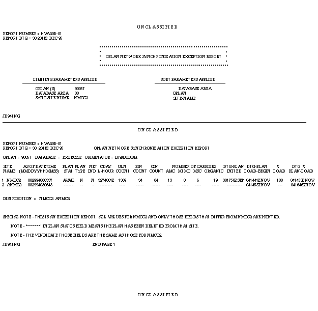
| 1 | Type "9005t" in ENTER OPLAN NUMBER, "b" in ENTER ONE OPTION. <RETURN>. | UF-001, SPAWN BATCH JOB, screen displays. |
| 2 | Type "e" in OUTPUT DISPOSITION. <RETURN>. | IF-V01, OPLAN NETWORK STATUS (Fig. 10-7), screen redisplays. |
Note: An example of the report is shown in Figure 10-10.
 |
Note: The standard "Transaction Queued, System Load May Cause Delays" message will appear when transmitting after putting an appropriate entry in the OPLAN block and selecting Option C.
Manual Synchronization. When the automatic sync does not solve the "out-of-sync" condition, the Network FM may need to do a selective site data recovery, S/F HU. This procedure is usually reserved for repairing a site after a complete recovery process, but may be used to fix missing individual or groups of ULNs, CINs, PINs, and carrier records. This is a network FM management function and will be covered in more detail during site recovery in Lesson 12.
That is TS3 mainframe synchronization. It is generally the responsibility of the Network FM, but as a site FM, you may find yourself assisting. With synchronization done, the next step in analysis is the audit, or who did what to whom! If something caused the network to get out of sync, it is in the best interest of all to find out why it happened so you can prevent it from happening again.
OBJECTIVE. From a list of possible answers, select the sequence of events for journalization and the conducting of audits for his/her site.
Tape Maintenance. Normally there are five tapes assigned to the journal function, but up to 40 tapes can be assigned. S/F HM provides a method to add, replace, or remove a tape from the journal index file. It is restricted to the site TDBM and requires UPD and IRM permissions. HM also allows the TDBM to produce a display of all tapes in the tape index file.
OBJECTIVE. Given a WWMCCS environment, conduct a JOPES audit.
Note: Navigate to the JOPES Master Menu in the exercise database.
| AUDIT REPORTS | ||
|---|---|---|
| Step | Activity | Anticipated Result |
| 1 | Type "ho" in SUBSYSTEM FUNCTION. <RETURN>. | IF-001, AUDIT REPORTS (Fig. 10-11), screen displays. |
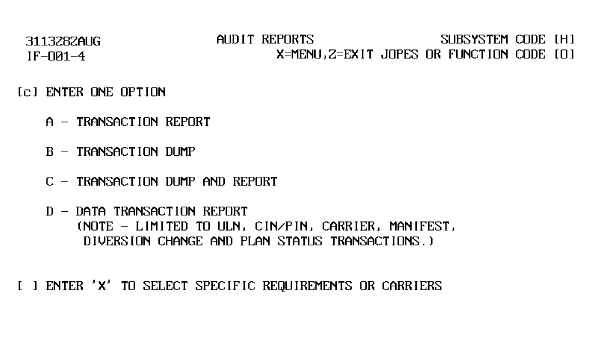 |
Transaction Dump, Option B. The Transaction Dump is a bit more expanded than the Transaction Report. It shows all qualifying transactions in unformatted 132 character lines. It is not very easy to read and requires some practice to learn how to find information quickly. Again, solely transaction oriented.
| AUDIT REPORTS | ||
|---|---|---|
| 2 | Type "c" in ENTER ONE OPTION. <RETURN>. | IF-002, AUDIT REPORTS (Fig. 10-12), screen displays. |
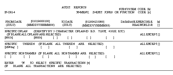 |
Note: "X" in All Except block excludes the preceding entries from the report. In this case, the two plans, the USERID, and Host listed would not qualify for this report.
| AUDIT REPORTS | ||
|---|---|---|
| 3 | Type "mmddyy000100" in FROM DATE. Type "mmddyy240000" in TO DATE. Type "e" in DATABASE EXERCISE-E. Type "9005t, 9096f" in SPECIFIC OPLAN. Type "jd94tng" in SPECIFIC USERIDS. Type "x" in ENTER 'X' TO SELECT SPECIFIC TRANSACTIONS. <RETURN>. | IF-003, AUDIT REPORTS (Specific Transactions) (Fig. 10-13), screen displays. |
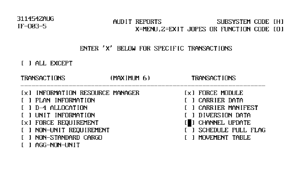 |
Note: Entering an "X" at All Except will exclude the information selected in the bottom half of the screen.
| AUDIT REPORTS | ||
|---|---|---|
| 4 | Type "x" in INFORMATION RESOURCE MANAGER, FORCE MODULE, and FORCE REQUIREMENT. <RETURN>. | UF-001, SPAWN BATCH JOB, screen displays. |
| 5 | Type "e" in OUTPUT DISPOSITION. <RETURN>. | IF-001, AUDIT REPORTS (Fig. 10-13), screen redisplays. |
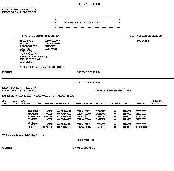
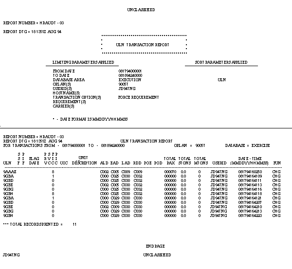
Note: An example of the report is shown in Figure 10-14.
 |
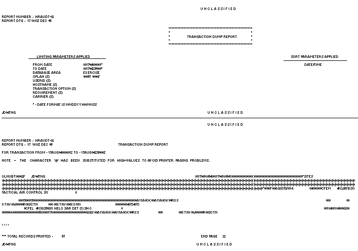 |
The Partial Transaction Report provides the FM with a list of all transactions that updated the system within the input parameters. The report provides the User ID (PJ) of the operator who executed a module against a plan. No specific actions like changes to cargo or passengers are listed. (The first three columns are JDSUP generated numbers used for control and auditing). Of more use is the Dump Report. The Transaction Dump Report is a transaction oriented Report in unformatted 132 character format. Functional data can be found there but with some difficulty in being certain exactly which information it is.
| AUDIT REPORTS | ||
|---|---|---|
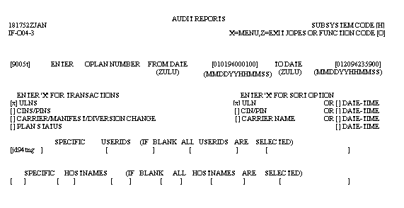
| 6 | Type "d" in ENTER ONE OPTION. <RETURN>. | IF-004, AUDIT REPORTS (ULNs) (Fig. 10-15), screen displays. |
 |
| AUDIT REPORTS | ||
|---|---|---|
| 7 | Type "9005t" in ENTER OPLAN NUMBER, "mmddyy000100" in FROM DATE, "mmddyy240000" in TO DATE, "x" in ULNS, "x" in ULN, "jd94tng" in SPECIFIC USERIDS, and <RETURN>. | UF001, SPAWN BATCH JOB, screen displays. |
| 8 | Type "e" in OUTPUT DISPOSITION. <RETURN>. | IF-001, AUDIT REPORTS (Fig. 10-11), screen redisplays. |
Note: An example of the report is shown in Figure 10-16.
 |
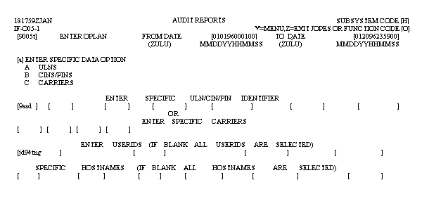
Audit Subsystem Data Qualification. The Audit subsystem has an additional capability to further limit (qualify) the amount of data that appears on the report. If on the HO screen, after selecting any of the four options, you place an "x" in the Enter 'X' to Select Specific Requirements and/or Carriers block, the IF-005 screen displays.
| AUDIT REPORTS | ||
|---|---|---|
| 9 | Type "d" in ENTER ONE OPTION and "x" in ENTER 'X' TO ...
CARRIERS. <RETURN>. |
IF-005, AUDIT REPORTS (Data Transactions) (Fig. 10-17), screen displays. |
 |
| AUDIT REPORTS | ||
|---|---|---|
| 10 | Type "9005t" in ENTER OPLAN, "mmddyy000100" in FROM DATE, "mmddyy240000" in TO DATE, "a" in ENTER SPECIFIC DATA OPTION, "9aad" in ENTER SPECIFIC ULN/CIN/PIN IDENTIFIER, "jd94tng" in ENTER USERIDS. <RETURN>. | UF-001, SPAWN BATCH JOB, screen displays. |
| 11 | Type "e" in OUTPUT DISPOSITION. <RETURN>. | IF-001, AUDIT REPORTS (S/F HO), screen displays. |
FM's Role. The FM uses these tools to solve problems. They can identify out of synchronization plans and audit activities to determine the cause. From the cause, corrective actions can be implemented and work assigned. (If you messed it up, you may be required to fix it.)
Up to this point, you have learned what the FM does and some TDBM functions to use when necessary to achieve objectives. We will now discuss the JOPES Monitor Subsystem (M), which allows you to watch transaction data processing within and between two sites. The permission needed to view these functions are QRY, and RPT if you wish to generate a report.
OBJECTIVE. Given a WWMCCS environment, monitor the JDS Update Processor and Interface Processor activities.
| JOPES MONITOR | ||
|---|---|---|
| Step | Activity | Anticipated Result |
| 1 | Type "m" in SUBSYSTEM and "e" in DATABASE. <RETURN>. | CF-017, JDS MONITOR (Fig. 10-18), screen displays. |
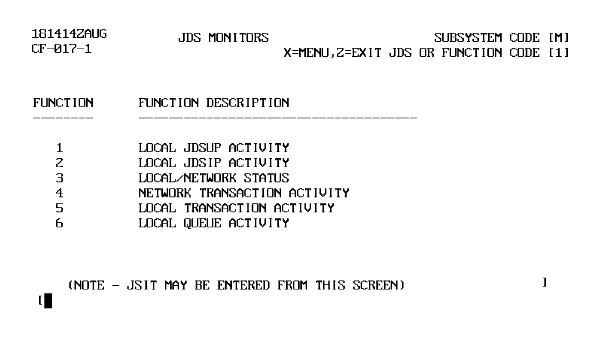 |
You will review each function.
| JDSUP STATUS MONITOR (M1) | ||
|---|---|---|
| Step | Activity | Anticipated Result |
| 1 | Type "1" in FUNCTION CODE, <RETURN>. | Enter (P)eek or (M)onitor displays. |
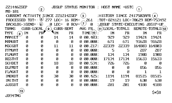
| 2 | Type "p". <RETURN>. | MO-101, JDSUP STATUS MONITOR (Fig. 10-19), screen displays. |
Note: Entering P will display five refreshed screen displays and then return to the M subsystem menu. Entering M will put the monitor in continuous display. If continuous display is selected, then enter $*$B to stop monitoring.
 |
| JDSUP STATUS MONITOR (M1) | |
|---|---|
| Item | Field Description |
| 1 | Monitor name and WIN site node you are logged on to. |
| 2 | Date/time of the current information displayed. |
| 3 | Date/time from which current activity totals are measured. |
| 4 | Date/time history reset. The JDSUP Monitor consists of two sections: current and history. |
| 5 | Total transactions processes since DTG in 3. |
| 6 | Transactions backlogged. |
| 7 | Transactions backlogged in the WIN receive queue. The backlogged transactions do not display totals like PROCESSED TO 5. |
| 8 | Transaction type. |
| 9 | Number of transactions dequeued and successfully processed since DTG at 3. The current activities
are divided into LOCAL and REMOTE sites.
As JDSUP processes each activity, it tallies in the PR(ocessed) columns. IN (from queue) and PR(ocessed) columns may differ slightly depending upon processing time and when JOPES activity is captured. Notice 5 PROCESSED TOT - reflects the same activity as shown in activity DICHET, FLAGKT, and JJDSDT. If PROCESSED TOT = 30, there may be more screens. All transactions equal the total. |
| 10 | Average processing time for each transaction type in minutes, seconds, and milliseconds. |
| 11 | Total transactions from HISTORY SINCE DTG. History totals are not reset to zero until JDSUP is cold booted due to a major malfunction. Local and remote transactions equal total transactions. |
| 12 | JDSUP and JDSIP status. |
| 13 | USERID that entered this monitor. |
| LOCAL JDSIP ACTIVITY (M2) | ||
|---|---|---|
| Step | Activity | Anticipated Result |
| 1 | Type "2" in FUNCTION CODE. <RETURN>. | Enter (P)eek or (M)onitor displays. |
| 2 | Type "p". <RETURN> | MO-201, JDS NETWORK INTERFACE PROCESSOR MONITOR AT XXXXX (Fig. 10-20), screen displays. |
Note: Enter P to display five screens/displays, M for continuous display, or 1-9 (sweep count to see a given number of screens/displays).
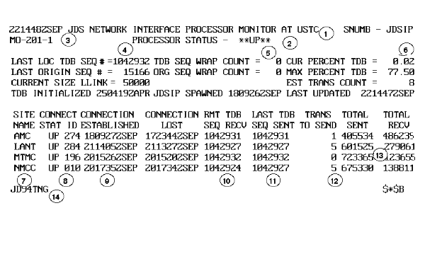 |
| JDS NETWORK INTERFACE PROCESSOR MONITOR (M2) | |
|---|---|
| Item # | Field Description |
| 1 | Monitor name and WIN site node you are logged on to. |
| 2 | JDSIP status. |
| 3 | DTG for information displayed. |
| 4 | Transaction numbers assigned sequentially by JDSIP to track transactions passing through IP. |
| 5 | Number of times sequence numbers have recycled through 999,999, the maximum sequence number allowed. |
| 6 | Shows the percentage of JDSIP file space used. JDSIP is the traffic cop between JDSUP and WIN. If a large transaction load exists, it is useful to know the JOPES saturation. |
| 7 | Host name and JDSIP status at remote sites. JDSUP status indicates the site is on-line and available to process transactions. DN status means the site is off-line or experiencing problems. There are three possible host sites. |
| 8 | Shows the connection ID (CID) number assigned by WIN Network Control Program (NCP). |
| 9 | Shows WIN line status of depicted sites.
If the times are the same for Connection Established and Connection Lost, the line is JDSUP and available for business between that site and your site. If Connection Established is later than Connection Lost, the line status is JDSUP or available. If Connection Lost is later than Connection Established, the line between the host and your site is DN. |
| 10 | Lists by the site sequence number of the last transaction received from a remote site. |
| 11 | Lists last transaction sequence number sent to a site. |
| 12 | Shows transactions backlog awaiting transmission to the indicated site. |
| 13 | Shows total transmissions sent to and received by the indicated site since JOPES was initialized or a new JOPES release installed. |
| 14 | USERID that entered this monitor. |
| JDS NETWORK SITE STATUS MONITOR (M3) | ||
|---|---|---|
| Step | Activity | Anticipated Results |
| 1 | Type "3" in FUNCTION CODE. <RETURN>. | Enter (P)eek, (M)onitor, or (#) sweep count displays. |
| 2 | Type "p". <RETURN>. | ENTER THE OLD STATUS ALARM TIME INTERVAL screen displays. |
| 3 | <SPACE>, <RETURN>. | MO-301, JDS NETWORK SITE STATUS MONITOR AT XXXXX (Fig. 10-21), screen displays. |
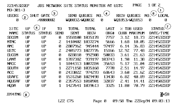 |
| JDS NETWORK SITE STATUS MONITOR (M3) | |
|---|---|
| Item # | Field Description |
| 1 | Displays page number and number of pages per monitor display. May contain up to 18 pages. |
| 2 | Number of users signed on to your site, includes local and remote terminals. |
| 3 | Indicates gate name and time gate shut. If a program malfunctions, a gate may remain shut. In this case, the gate controlling the WIN receive queue is hung, delaying JDSUP and JDSIP processing. Time displays in hours, minutes, and seconds. |
| 4 | Name of last send queue processed by JDSIP and the last send queue created by UP. The WIN queues (SEND and RECV) have a capacity of 500 transactions per queue file. The files are allocated dynamically and limited only by machine disk space. |
| 5 | Name of last receive queue processed by JDSUP and the last receive queue created by IP. |
| 6 | UP/IP status at remote site. |
| 7 | DTG of last update by individual site. |
| 8 | USERID that entered this monitor. |
| JDS NETWORK STATUS FILE MONITOR (M4) | ||
|---|---|---|
| Step | Activity | Anticipated Result |
| 1 | Type "4" in FUNCTION CODE. <RETURN>. | Enter (P)eek, 1-4 (sweep count), or (M)onitor displays. |
| 2 | Type "p". <RETURN>. | Enter (C)onnected Sites, (L)ist Sites, (R)eporting Sites, or (A)ll Sites displays. |
Note: The four options were useful when there were 20 sites in the network and GCCS JOPES did not exist.
| JDS NETWORK STATUS FILE MONITOR (M4) | ||
|---|---|---|
| 3 | Type "c". <RETURN>. | MO-401, JDS NETWORK STATUS FILE MONITOR AT XXXXX (Fig. 10-22), screen displays. |
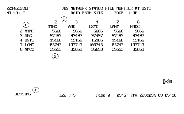 |
 JDS NETWORK STATUS FILE MONITOR (M4) |
|
|---|---|
| Item # | Field Description |
| 1 | Originating site. |
| 2 | Receiving site. |
| 3 | Last transaction number sent from the originating site. Last transaction number received from the originating site. |
| 4 | USERID that entered monitor. |
| TRANSACTION ACTIVITY MONITOR (M5) | ||
|---|---|---|
| Step | Activity | Anticipated Result |
| 1 | Type "5" in FUNCTION CODE. <RETURN>. | MO-501, TRANSACTION ACTIVITY MONITOR (Fig. 10-23), screen displays. |
Note: This is a timed screen, no other user entries.
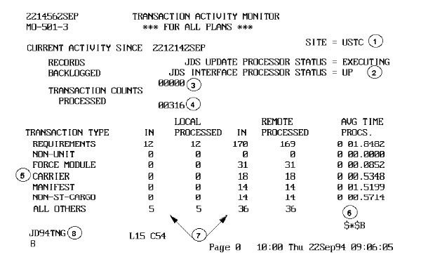 |
| TRANSACTION ACTIVITY MONITOR (M5) | |
|---|---|
| Item # | Field Description |
| 1 | Site name. |
| 2 | UP and JDSIP status. |
| 3 | Number of transactions waiting in the JDSUP queue. |
| 4 | Total entries listed under Local Processed and Remote Processed. |
| 5 | Transaction Type categories divided into 6 major areas. All Other contains those transactions that do not fit into one of the six major categories. |
| 6 | Average processing time for all transactions processed through each category. Time shown in minutes, seconds, and milliseconds. |
| 7 | Number of transactions received by the JDSUP for processing. Numbers should approximate, but not exceed, the numbers shown in Processed. |
| 8 | USERID that entered this monitor. |
| UPDATE QUEUE STATUS MONITOR (M6) | ||
|---|---|---|
| Step | Activity | Anticipated Result |
| 1 | Type "6" in FUNCTION CODE. <RETURN>. | Enter (P)eek or (M)onitor screen displays. |
| 2 | Type "p". <RETURN>. | MO-601, UPDATE QUEUE STATUS MONITOR AT XXXXX (Fig. 10-24), screens displays. |
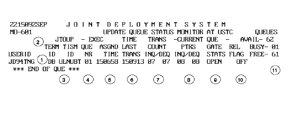 |
| UPDATE QUEUE STATUS MONITOR (M6) | |
|---|---|
| Item # | Field Description |
| 1 | USERID initiating the transaction. |
| 2 | Two letter terminal identification from which the transaction originated. If no terminal ID displays, the job is probably a batch job that was submitted and the user logged off the terminal. |
| 3 | Transactions listed by Transaction Independent Service Module (TSM or TISM) ID. The TISM ID column heading is misleading and should read TSM or TISM. |
| 4 | Queue number assigned as each transaction logs into the Update queue. |
| 5 | Time transaction assigned to Update queue. |
| 6 | Time transaction transmitted to UP. |
| 7 | Tracks TRANS COUNT INQ/DEQ (transaction count, into the queue/out of the queue). The INQ/DEQ represents the number of transactions being processed; however, the exact number cannot be deduced. The two-position fields cycle between 00 and 99. |
| 8 | Indicates update queue and current pointers are functioning properly if numbers are changing. The CURRENT PTRS, INQ/DEQ (current update queue program pointers) are for the nest input queue (INQ). These numbers are displayed in binary code, and the value @ is not a mistake, but a character that appears now and then to reflect the binary count is taking place. |
| 9 | Displays the status of the queue gate as either Open or Close. Gates control file access and prevent many JOPES activities from writing or reading a file at the same time and scrambling records, causing the database to become unusable. |
| 10 | Rel Flag (release flag) shows the internal switch position that determines whether the queue is ready for JDSUP release (OFF = hold, ON = release). |
| 11 | Displays available update queues. The update queue has 62 available queues to log in 12 transactions each. The Busy and Free positions must total 62, if added. |
OBJECTIVE. Given a WWMCCS environment, manipulate personal JOPES TPFDD files.
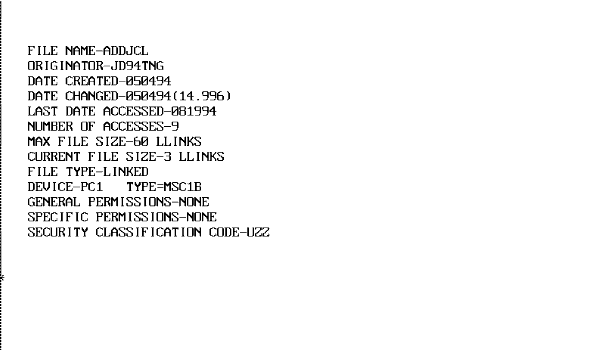 |
File Usage. Below are some of the reasons a functional user or the FM may consider creating files on the mainframe.
As a Working Medium. Files may be used as a temporary working medium to manipulate or change data. This is probably the most frequent usage of files for all of the JOPES application.
As a Transfer Vehicle. On the mainframe, files are more efficient than tapes when transferring data between or within a JOPES site. The user does not have to rely on the system operator at both ends to load tapes with those associated delays. However, users should ensure that files are constructed properly, are large enough, and have the correct security classifications (correct attributes) when transferring data between sites. Files are also used to transfer data from the mainframe to the hard drive on your PC workstation or from your workstation to the mainframe.
As a Save/Archive Vehicle. As long as there is ample disk space, the disk can be used as permanent storage. Users should consider making backups of critical data for out-of-system storage since disks do occasionally crash.
OBJECTIVE. Given a WWMCCS environment, use the FTS software to copy a file from one host computer to another host computer.
Note: From the timeshare prompt, type "jdac fts" to navigate to the FTS prompt.
Note. A TPFDD file is resident on the primary host for you to transfer to the backup host. The file, the last item in the cat/file string, does not need to exist at the receiving host, but a catalog (and subcatalogs if desired) must. Those catalogs do exist at the backup host for your use. The files at the primary host are {instructor created}. The catalog at the backup host is {instructor created}. FTS is used to transfer files.
| TRANSFER DATA BETWEEN A SITE | ||
|---|---|---|
| Step | Activity | Anticipated Result |
| 1 | Type "repl {instructor created} at nmcc2 with {instructor created} at anmc2". <RETURN>. | => (FTS prompt) displays. |
| 2 | Type "exec ps m". <RETURN>. | CMID XXXX (Fig. 10-26) screen displays. |
Note: The "exec ps m" command tells the system to execute the job, post its status, and monitor the job until completion. After the job completes, the screen will post with the FTS prompt.
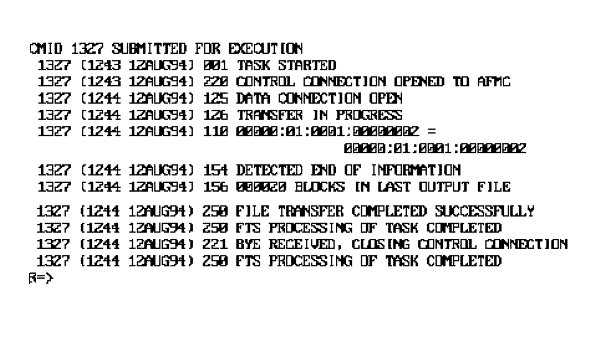 |
Note: Screen will display the job's progress as it goes through each required step, keeping you informed as to what is happening. Upon completion, the screen returns to the FTS prompt. Type "dac tss" to return to time sharing.
| TRANSFER (COPY) A FILE WITHIN A SITE | ||
|---|---|---|
| Step | Activity | Anticipated Result |
| 1 | Type "cpy {instructor created};{instructor provided}" at the TSS prompt. <RETURN>. | Copied # llink. |
| 2 | Type "rc" at the TSS prompt. <RETURN>. | TSS prompt "*" displays. |
Note: The rc command is for "remove and clear files." This will unbusy the files.
OBJECTIVE. Given JOPES operating in a WWMCCS environment, save an OPLAN to a tape.
Transfers. Another aspect of tape use is the ease it provides the FM/TDBM to transfer large amounts of data between sites. Many of the reference files and site recovery files are transmitted in this way, either electronically or manually (handcarried).
Archives. This is the same as backup, but there is another option, H4, which is restricted to the TDBM. This function permits the TDBM to backup several OPLANs onto the same tape.
Perform a Tape Save. Most of the tape saves accomplished by the FM involve the saving of data that is resident on the IDS/I database. The H3 Subsystem/Function of (JDS) JOPES saves information in JDS transaction format, while the B8 Subsystem/Function saves in TPFDD (JOPS) format.
| OFFLOAD OPLAN | ||
|---|---|---|
| Step | Activity | Anticipated Result |
| 1 | Type "a" in ENTER OPTION. <RETURN>. | IF-302, OFFLOAD OPLAN (Fig. 10-27), screen displays. |
 |
| OFFLOAD OPLAN | ||
|---|---|---|
| 2 | Type "9096f" in ENTER OPLAN TO BE OFFLOADED and {xxxxx} in ENTER TAPE NUMBER, <RETURN>. | IF-303 VERIFY OFFLAND OPAN (fig. 10-28). screen displays. |
 |
| OFFLOAD OPLAN | ||
|---|---|---|
| 3 | Type "9096f" in OPLAN NUMBER and {nnnnn} in TAPE NUMBER. <RETURN>. | SPAWN BATCH JOB screen displays. |
| 4 | Type "u" in SECURITY CLASSIFICATION and "j" in OUTPUT DISPOSITION. <RETURN>. | SNUMB XXXXX displays. |
| 5 | Press <SPACE> <RETURN>. | IF-301, OFFLOAD/RELOAD OPLAN (H3), screen displays. |
Note: You may monitor this job via the JMON command at the TSS prompt.
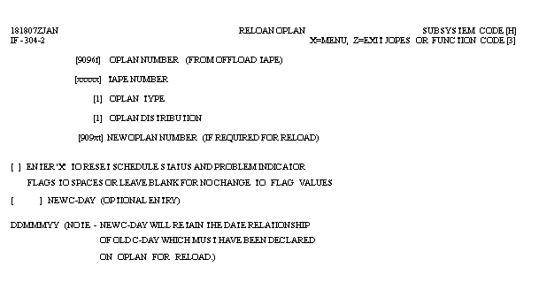
| RELOAD OPLAN | ||
|---|---|---|
| Step | Activity | Anticipated Result |
| 1 | Type "b" in ENTER OPTION. <RETURN>. | IF-304, RELOAD OPLAN (Fig. 10-29), screen displays. |
 |
| RELOAD OPLAN | ||
|---|---|---|
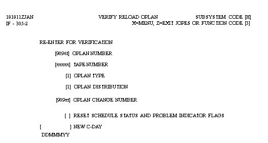
| 2 | Type "9096f" in OPLAN NUMBER, {xxxxx} in TAPE NUMBER, "l" in OPLAN TYPE, "l" in OPLAN DISTRIBUTION, and "909xt" in NEW OPLAN NUMBER. <RETURN>. | IF-305, VERIFY RELOAD OPLAN (Fig. 10-30), screen displays. |
 |
| RELOAD OPLAN | ||
|---|---|---|
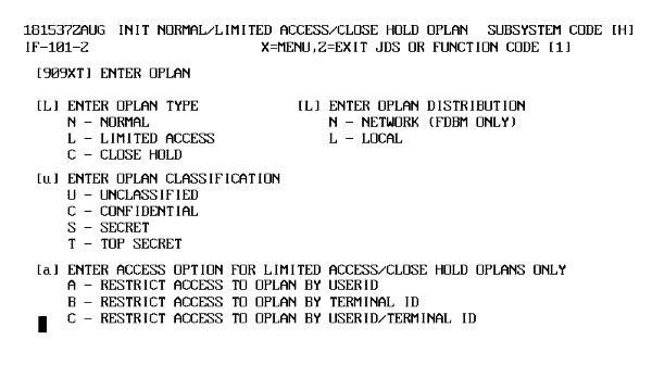
| 3 | Type "9096f" in OPLAN NUMBER, {xxxxx} in TAPE NUMBER, "l" in OPLAN TYPE, "l" in OPLAN DISTRIBUTION, and "909xt" in OPLAN CHANGE NUMBER. <RETURN>. | IF-101, INIT NORMAL/LIMITED ACCESS/CLOSE HOLD OPLAN (Fig. 10-31), screen displays. |
 |
| RELOAD OPLAN | ||
|---|---|---|
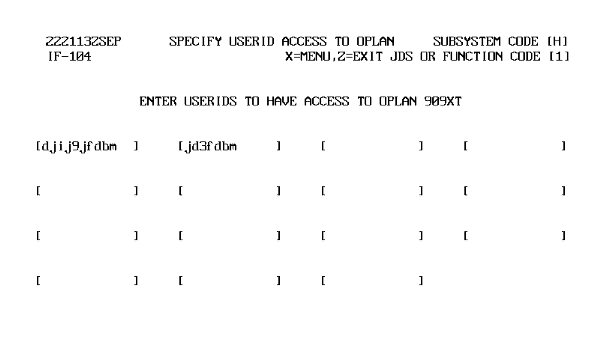
| 4 | Type "u" in ENTER OPLAN CLASSIFICATION and "a" in ENTER ACCESS OPTION FOR LIMITED ACCESS/CLOSE HOLD OPLANS ONLY. <RETURN>. | IF-104, SPECIFY USERID ACCESS TO OPLAN (Fig. 10-32), displays. |
 |
| RELOAD OPLAN | ||
|---|---|---|
| 5 | Type "dj9jfdbm" and "jd3fdbm" in ENTER USERIDS TO HAVE ACCESS TO OPLAN 909XT. <RETURN>. | The SPAWN BATCH JOB screen displays. |
| 6 | Type "u" in SECURITY CLASSIFICATION and "j" in OUTPUT DISPOSITION. | SNUMB XXXXX displays. |
| 7 | Press <SPACE> <RETURN>. | IF 301, OFFLOAD/RELOAD OPLAN screen displays with TRANSACTION QUEUED, SYSTEM LOAD MAY CAUSE DELAY. |
Note: There are some special rules or conditions that apply when initializing an OPLAN with H1 and/or loading with H3 or HK. Quite often, people are surprised when these conditions occur because they are not familiar with the design. Tables 10-8 and 10-9 summarize the possible conditions.
| OPLAN INIT/LOAD RELATIONSHIP | |||
|---|---|---|---|
| OPLAN Type | OPLAN Distribution | OPLAN Status After H1 INIT | OPLAN Status Prior To HK Load |
| NORMAL | LOCAL | LOAD | LOAD |
| NORMAL | NETWORK | LOAD | LOAD |
| LIMITED ACCESS | LOCAL | AVAIL | AVAIL |
| LIMITED ACCESS | NETWORK | LOAD | LOAD |
| CLOSE HOLD | LOCAL | AVAIL | AVAIL |
Note: If you initialize an OPLAN (H1), it will be in the above status depending on the OPLAN type and distribution selected. Under any of the above circumstances, HK can load the plan. If, however, you reset the plan type (H2), you may or may not be able to use HK to load. For example, if a close hold OPLAN is changed to normal, it will change to available status and not accept an HK load (Table 10-9).
| H2/PLAN TYPE RELATIONSHIP | |||||
|---|---|---|---|---|---|
| OPLAN Type | Reset To | OPLAN Distribution | OPLAN Status | Use S/F HK To Load | Remarks |
| CLOSE HOLD | LIMITED ACCESS | LOCAL | AVAIL | YES | |
| CLOSE HOLD | NORMAL | LOCAL | AVAIL | NO | NORMAL OPLAN Must be in LOAD status to use S/F HK |
| LIMITED ACCESS (Network Distribution) | NORMAL | NETWORK | LOAD | YES | |
| LIMITED ACCESS (Local Distribution) | NORMAL | LOCAL | AVAIL | NO | See Remarks above |
You have covered some of the aspects of file and tape management and you have built an OPLAN. Now you are going to add those Marine records that are in a file at both hosts. Using the merge capability to add them to the database. Merging data is something that can happen often. TPFDDs are usually built by the service components of the supported CINCs and then combined into a single database. The combining of those service TPFDDs is usually done by the FMs at the supported command.
OBJECTIVE. Given a TS3 WWMCCS environment, merge a JOPES TPFDD file into an OPLAN.
Files. Data may reside on an archived or personal file, and you may have to extract it from its storage location before merging it with another plan. You could also be "air-gapping" records that had been created or manipulated in one of the other JOPES applications such as JFAST.
Tapes. Tapes are generally used to store large amounts of data and provide out of system storage. Many functions in JOPES make use of the archival capability of tapes. Provisions are made for merging these tapes directly into the database.
That was a very brief review of some of the sources of data for a merge. You previously transferred a file from the primary host to the backup host, so it is resident at both places. You will now merge that file into your OPLAN.
Note: Ensure that each student's plan has had sufficient time to load. You can check the status with A3, then, when the plan has completed loading, go to the B3 S/F in the exercise database.
| MERGE TPFDD DATA INTO A JDS OPLAN | ||
|---|---|---|
| Step | Activity | Anticipated Result |
| 1 | Type "909xt" in TARGET OPLAN, and {instructor created} in SOURCE TPHOLD FILE. <RETURN>. | UF-001, SPAWN BATCH JOB, screen displays. |
| 2 | Type "u" in SECURITY CLASSIFICATION and "j" in OUTPUT DISPOSITION. <RETURN>. | Your SNUMB NUMBER will appear. Space Transmit to return to REQUIREMENTS menu. |
Now that you know how to add TPFDD formatted data to your OPLAN, what do you use to add transaction formatted data?
OBJECTIVE. Given a WWMCCS environment, describe the process of updating a JDS OPLAN using transactions from an external source.
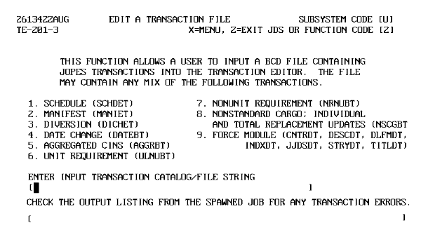
Note: All data entered into the mainframe database is edit checked. If you fill out a BL screen, each data entry is checked for validity or accuracy, i.e., does the GEO exist, is the UTC valid, etc. All of these edit checks were included in the U2 TE process, so external information entering the database via other means is as stringently checked. Certain JOPES S/Fs that take plans off the database, reenter plans into the database, merge plans into the database, or make mass changes to the database (H3, H4, HK, B3, and F6) are required to go through a minimal reedit when executed. The minimum check includes service, PROVORG, cargo category code, and alpha/numerics/invalid characters.
 |
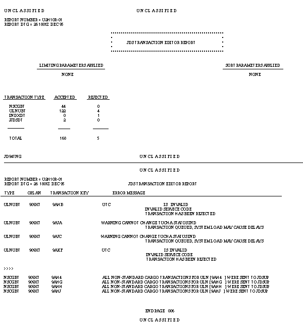 |
Note: The report lists the transaction type in TDBM language, the OPLAN affected, the database item affected, and what caused it not to update. Translation of the Type block can be found in TD 18-14-1, Vol 9, JDS Transaction Editor Users' Manual.
Transfer Issues. The transfer to JOPES requires the transactions to be in a specific format to match the receiving TPFDD in the IDS/I database. Therefore, you need to make allowances for the following kinds of problems before using the S/F U2 Transaction Editor:
The U2 editor will reject incorrect TUCHA Status Indicator codes.
You can use DART to correct it (legal entry "blank" or "x") prior to passing the records back to the DPS 8000.
The U2 editor will also reject invalid CCCs.
Again you can use DART to remove the invalid TUC code prior to the transfer.
The U2 process splits nonstandard cargo transactions for new ULNs into transaction types and processes them separately. When the U2 processes the transactions out of order (changed before created), the record rejects. Remember, an "add" transaction cannot happen to a record that already exists, a "change" or "delete" transaction can only occur to a record that already exists or it will be rejected.
The best way to troubleshoot U2 problems is to carefully review the Reject Report and adjust the TPFDD to compensate for the problems or do the straight B3 merge.
Now that you know how to get OPLAN records into the database, it is time to turn your attention to keeping the reference files that assist in building these OPLANs current.
OBJECTIVE. From a list of possible answers, select those that reflect the FM's duties as they relate to the reference files.
| REFERENCE FILES | |
|---|---|
| File Name | Function and Characteristics |
| TUCHA | Type Unit Characteristics File. The TUCHA file contains UTCs and related data to assist in developing force movement requirements for operation plans. UTCs are standard coded representations of logically similar kinds of military organizations. TUCHA is used to register, maintain and validate UTCs, and provide movement characteristics data for all UTCs which are deployable, are fixed composition, and require common user transportation support. Data are submitted for TUCHA processing whenever it is necessary to register a UTC or add, change, or delete information pertaining to a type of unit. |
| GEOFILE | Specified Geographic Locations File. The GEOFILE provides appropriate location information (e.g., point name, country/state code, installation type code, coordinates, etc.) for all registered geolocation codes. The GEOFILE is used to validate geolocation codes used in JOPES and to provide expanded information for displays and reports. |
| SORTS | Status of Resources and Training System File. This file contains readiness, availability, and other status information on reported units. It provides the most current status and identity of these units. |
| CHSTR | Characteristics of Strategic Transportation Resources File. The CHSTR file provides an automated source of reference material on the characteristics of strategic transportation resources. This file contains physical and operating characteristics of aircraft and ships used in operation planning to transport military units, cargo, and/or personnel. CHSTR data discretely identify the characteristics of aircraft and ships for transportation planning. Essential elements for aircraft are speed, range, load and unload time for passengers and cargo, capacity for passengers and cargo (short tons), and utilization rates. Data for ships include loaded and unloaded speed, length, beam, draft, load and unload time, discharge mode, passenger and/or cargo capacity, and landing craft embarked. |
| SDF | Standard Distance File. The SDF contains route distance for both air and sea routes used in deployment operations. SDF contents are unique to each user site. |
| APORTS | Aerial Ports and Air Operations Bases File. The APORTS file provides an automated source of reference material on airfield installation throughout the Free World. APORTS contains information on physical and operating characteristics of reportable airfields. Airfield characteristics include number of aircraft arrivals and departures, parking, and reception capability; apron information, throughput for passengers and cargo as computed from calculated reception, reported clearance, and discharge capabilities; and remarks as input by site-unique programs. |
| ASSETS | Transportation Assets File. The ASSETS file provides an automated source of reference material on the availability of strategic transportation resources in accordance with the JSCP. ASSETS contains time- phased availability of common carrier airlift and sealift resources which can be used in the deployment aspects of operation planning. ASSETS data include operation planning information for total aircraft resources and their time-phased availability by geographic location. |
| PORTS | Port Characteristics File. This PORTS file provides an automated source of reference material on seaports of the Free World. PORTS contains information on the physical and operating characteristics of seaports. Data include port description, harbor description, wharf description, berth data, throughput capacity, channel data, anchorage protection, storage capacity, mechanical handling equipment, and remarks. |
| TUDET | Type Unit Equipment Detail File. The TUDET file supports the TUCHA system through its use to validate Equipment Identification Codes (EIC) and to provide data for TUCHA cargo category detail records. Physical characteristics for certain types of unit equipment are contained in the TUDET file. This equipment includes nonpalletized wheeled and tracked vehicles, non-self-deployable aircraft which are uncrated, floating craft, hazardous cargo, and any item greater than 35 feet in any dimension. |
| LFF | Logistics Factors File. The LFF provides users with Service approved resupply and critical item/essential sustainment item (ESI) planning factors for use in the deployment of joint operation plans. The factors, as adjusted by the planner are used by the Movement Requirement Generator (MRG) and Logistics Sustainment Analysis and Feasibility Estimator (LOGSAFE). Factors may be varied according to theater of operation. These are heavy, moderate, light, reserve, and forces that are not operationally employed (noncommitted). Resupply factors may be provided as consumption rates specified by pounds-per-man/per- day or UTC. ESI may be provided by pounds-per-man/per-day or by capabilities apportioned to the CINC or the Services and DLA. |
WASSO Processes Package. One of the documents in the package is the transmittal slip. The transmittal slip identifies which file is being updated, instructions for the TDBM on the number of records, a time frame for upload, and a brief description of changes that have been implemented. The WASSO passes a copy of this document to the TDBM and sends the tape containing the file to the tape library.
FM Notified. After the WASSO notifies the TDBM, the TDBM reviews the document and contacts the FM to schedule the appropriate amount of down time for JOPES. JOPES must be unavailable to the users during the upload period for two reasons:
In addition, the users may find that the information they are accessing on the system will change as the load is being conducted.
Users Notified. After the FM is notified, he must coordinate with the TS3 users to determine the best time to have the files updated. Usually the files are delivered with a window of opportunity from the source. However, the FM must use tact and tenacity to ensure that the files get updated within that window. Consideration should be given for critical and ongoing operations. Do not forget, users may use the backup site to continue processing. This may require some planning, especially if the user needs local plans.
TDBM Update Files. The FM coordinates with the TDBM to accomplish the update. Under most circumstances, the update will consume approximately four hours.
Users Notified. The FM then goes through the same channels to notify all users that the system is again accessible. The responsibility of the users and the FM does not stop here. Users and the FM should be keenly aware of any impact that the files may have on previous work. A friendly reminder from the FM to the users to validate critical work that was previously done against the new reference file may be in order.
As you can see, the FM has limited involvement in the actual updating of the reference files. You will now do a short review before beginning the next lesson.
Summary. During this lesson, you have considered several topics. You started out with some system analysis and used the monitoring subsystem to assist. You also worked with some personal files saved on the mainframe and transferred a file from one mainframe to the other. You also worked with tapes by saving an OPLAN to one and then reloading it back into the JOPES database. You also reviewed the procedures used to update the reference files that are used to assist in creating OPLANs.